Anyway.. down to business
You will need the following :-
- @ PSX Link Cable (look on eBay)
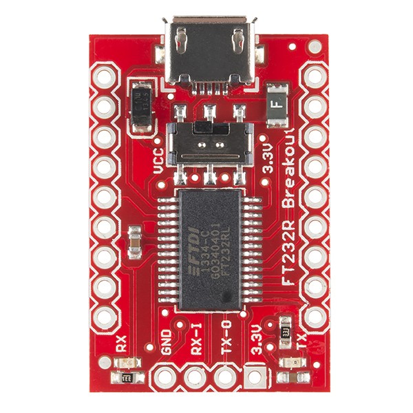
@ 3.3v FTDI Module (This MUST be a genuine FTDI232 module – if its a module with a counterfeit FTDI chip on it, it WILL NOT WORK!) It also must have ALL handshaking lines present (RTS/CTS/DSR/DTR)
@ Either ft_prog232r (for linux - http://rtr.ca/ft232r/ )
or ft_prog (for Windows - http://www.ftdichip.com/Support/Utilities.htm#FT_PROG )
@Multimeter
@Soldering Iron
@ Some patience..
First job is to get your PSX link cable. Personally I would chop it clean in half so you have a spare bit of cable to play with for a second spare cable or for another project. Then you need work out which pins correspond to which coloured wires within the cable. You can do this with the resistance mode on the meter.
Easiest way I found it to hold the connector firmly somewhere and type the corresponding pin number in a text document, followed by the colour. Once finished you should have something that resembles the following
- 1 – brown
2 – pink
3 – green
4 – black
5 – yellow
6 – red
7 – not connected
8 – orange
Then, cross reference the colours with the pinouts here http://www.psxdev.net/forum/viewtopic.php?f=47&t=66
- 1 – brown RTS
2 – pink GND
3 – green DTR
4 – black CTS
5 – yellow TXD
6 – red DSR
7 – not connected
8 – orange RXD
Once you are 100% sure that your pin/colour mapping is correct you can fire up your soldering iron and get soldering. You need to connect the pins up as follows :-
- PSX FTDI Module
RTS CTS
GND GND
DTR DSR
CTS RTS
TXD RXD
DSR DTR
RXD TXD
Once this is all done you can move on to reprogramming the eeprom on the FTDI Module. I did it on Linux but it is easier to do on Windows.
For linux just download and unpack the archive to a folder. Then open a terminal and cd to the folder and type make. That should be it.
Once the compilation has finished (it only takes a few seconds).. connect the FTDI to your machine and type
Code: Select all
sudo ./ft232r_prog -–dumpNotice in the dump window towards the bottom you can see rts_inverted = 0.. this is what we are going to change. The reason being is the PSX uses inverted handshaking, and lucky for us the FTDI module allows to invert these lines without the need for any extra hardware. To do this type the following line into the terminal
Code: Select all
sudo ./ft232r_prog --invert_rts --invert_cts --invert_dtr --invert_dsrThen you should see the following :-
Once that has completed type
Code: Select all
./ft232r_prog –dump For windows users you would need to use ftprog from FTDI.. the screenshot below shows the correct screen you need to use, just check the boxes for inverting RTS, CTS, DSR and DTR and write back to the device.. simples. Make sure you read the settings back after unplugging and replugging the FTDI back in to your PC.. just to make sure the settings have been written correctly.
If you get an error the likelyhood is you have a module with a clone FTDI chip on it. The problem is they dont allow eeprom programming, they probably dont even have one. If you have got one by mistake either return it or re-use it as a simple PSXSERIAL cable, they work fine for that.
Once you have done thatyou just need to set up your Yaroze environment in dosbox, and also add the line to the dosbox-0.74.conf file for the serial port eg :-
serial1=directserial realport:ttyUSB0 (linux)
serial1=directserial realport:COM5 (windows)
check either dmesg on linux or device manager on Windows to see what TTY/COM port is being used.
Then you need to burn the cracked boot disc for the PlayStation side and also copy the Yaroze environment over to dosbox to use and you are done.
Hope its of some use. I will revise it and add more screenshots and pictures to make it easier to understand.
Just to add.. I have used an FTDI which was configured for 5v use and it worked fine, but i would really recommend getting the proper 3.3v module just in case.
Have fun and happy Yarozing!!


 , "PlayStation",
  ,
,  , "DUALSHOCK", "Net Yaroze" and "PSone" are registered trademarks of Sony Computer Entertainment Inc.
  .
.