

Don't forget to repair the cut trace for logging the disc's scex string.
Requiring people to cut the trace or to wire GATE shouldn't matter much, or you could tell them to do either one as pleased. Simpliest would be wiring GATE to GND (I've tested that, and it works fine, but I don't know if any modchips have ever used that method? And if not: is there any reason for not doing so???)
Relying on the internal "high-z pullup" in the HC05 seems a bit weak. You probably won't get instant low-to-high transitions with it (though with the slow 250 bit/s signal, instant transitions may be not that important). Better output a HIGH level, or leave the old trace connected and use that as pullup.
Okay, you have only one wire for DATA+SYNC on Arduino pin 8, but where does that wire connect to? The modchips known to me wire WFCK (SPU.Pin5) to SYNC (IC723.Pin17), and the modchip's SCEX signal to DATA (SPU.Pin42); that, for a PSone board with 208pin CXD2938Q SPU. Do you have the Arduino pin 8 wired to any of those pins, too, or does it go somewhere else?
PSNee further development

http://www.heymunky.co.uk/wp-content/up ... 12f629.jpg
Arduino pin 8 is simply connected to "point 6" in that picture.
On every PSX, there is just one "data" point where the SCEX string gets injected to. All the other points are merely helping out

Arduino pin 8 is simply connected to "point 6" in that picture.
On every PSX, there is just one "data" point where the SCEX string gets injected to. All the other points are merely helping out
No worries, I'm using a fresh console. PU-22 must be the most widely available revisionDon't forget to repair the cut trace for logging the disc's scex string.
Interesting that this works. But well, whenever you pull something that has other stuff on it to ground, every time that other stuff outputs, it will be a short circuit and lots of current drawn on that chip. It's best to avoid it or keep the interference low (which is what I suspect modchips do as well, by setting their Gate pin to high-z.)Simpliest would be wiring GATE to GND (I've tested that, and it works fine, but I don't know if any modchips have ever used that method? And if not: is there any reason for not doing so???
Log from a PAL game on a PAL SCPH-7502:
I added a couple comments
And here is a 2nd attempt with the same conditions (but the init stuff cut out):
And one more:
Now here's logs from a copy of the same disc. Since there's no authentication on this CD-R, the log is much longer.
The console doesn't get the key it wants.
1st:
2nd:
I added a couple comments
And here is a 2nd attempt with the same conditions (but the init stuff cut out):
And one more:
Now here's logs from a copy of the same disc. Since there's no authentication on this CD-R, the log is much longer.
The console doesn't get the key it wants.
1st:
2nd:
Cool, that's interesting! There are some general differences between original and copy...
-- Original disc uses ADR/Control=41h for Point A0h (and for the Data Track)
-- CDR-R disc uses ADR/Control=41h for Point A0h,A1h,A2h (and for the Data Track)
-- Original disc has Lead-in addresses ending at 07:59:74 (probably so, or somewhere near there)
-- CRD-R disc has Lead-in addresses ending at 99:59:74
I've no idea if the "correct" ADR/Control value for Point A1h,A2h is officially defined somewhere, going by the above it can be this or that (so better handle both cases in your code).
And for the New SCEX signal, just for reference, this is how it works at HC05 side: http://problemkaputt.de/psx-spx.htm#cdr ... alspucombo
So special values can show up in 4th..7th bytes (depending on upper 4bit of the "xy" random value, the lower 4bit are always 0001b). That four bytes are the normally MM:SS:FF:00 (time within lead-in, and reserved zero byte).
And, as seen in the logs, everything else seems to contain normal unmodified SUBQ values (so TOC reading work as normal, without getting disturbed by the special SCEX packets). No, wait. There's also that feature with the Dummy-byte, which needs to be different from the character byte, so the PSX would need to destroy 8th..10th byte in some cases (or it's just hoping that those bytes will OR up to a value different from the character).
In the log, this are "C" and "E" from the PAL disc's "SCEE" string:
Theoretically they should be separated by a packet with 00h byte, which seems to be missing in the log, the second "E" seems to be missing, too, and can't see the leading "S", but well, the log is good enough to figure out how the data looks like.
One small/interesting detail is that they do just seem to repeat the character for each of the OR values (eg. "43h OR 43h", rather than doing something like "40h OR 03h").
Oh, and now seeing the logs. Sorry - some of my earlier suggestions have been total nonsense & crap:
The CRC isn't transferred on those pins, so no way to check it.
And, recognizing Point=01h..99h as Lead-in values would be nice, but there's no way to distinguish them from Track=01h..99h values in the Position data outside of Lead-in area (or it would require to compare several packets, eg. for sensing repeatedly increasing Point values, or sudden jumps in the MM:SS:FF values in 8th..10th byte).
-- Original disc uses ADR/Control=41h for Point A0h (and for the Data Track)
-- CDR-R disc uses ADR/Control=41h for Point A0h,A1h,A2h (and for the Data Track)
-- Original disc has Lead-in addresses ending at 07:59:74 (probably so, or somewhere near there)
-- CRD-R disc has Lead-in addresses ending at 99:59:74
I've no idea if the "correct" ADR/Control value for Point A1h,A2h is officially defined somewhere, going by the above it can be this or that (so better handle both cases in your code).
And for the New SCEX signal, just for reference, this is how it works at HC05 side: http://problemkaputt.de/psx-spx.htm#cdr ... alspucombo
So special values can show up in 4th..7th bytes (depending on upper 4bit of the "xy" random value, the lower 4bit are always 0001b). That four bytes are the normally MM:SS:FF:00 (time within lead-in, and reserved zero byte).
And, as seen in the logs, everything else seems to contain normal unmodified SUBQ values (so TOC reading work as normal, without getting disturbed by the special SCEX packets). No, wait. There's also that feature with the Dummy-byte, which needs to be different from the character byte, so the PSX would need to destroy 8th..10th byte in some cases (or it's just hoping that those bytes will OR up to a value different from the character).
In the log, this are "C" and "E" from the PAL disc's "SCEE" string:
Code: Select all
1 0 4 7 43 43 0 17 12 38 9F 7F  resets:  21    ;43h = "C" (random seems to be xy=C1h)
1 0 6 45 45 45 45 23 34 28 FC FF resets: 14 ;45h = "E" (random seems to be xy=F1h)One small/interesting detail is that they do just seem to repeat the character for each of the OR values (eg. "43h OR 43h", rather than doing something like "40h OR 03h").
Oh, and now seeing the logs. Sorry - some of my earlier suggestions have been total nonsense & crap:
The CRC isn't transferred on those pins, so no way to check it.
And, recognizing Point=01h..99h as Lead-in values would be nice, but there's no way to distinguish them from Track=01h..99h values in the Position data outside of Lead-in area (or it would require to compare several packets, eg. for sensing repeatedly increasing Point values, or sudden jumps in the MM:SS:FF values in 8th..10th byte).
Just noticed that the logs (both original and CD-R) have each Point repeated three times (official specs say somthing that lead-in stuff must be on three consecutive sectors, though I think they don't say if it needs to be have the same Point value, anyways, on these discs it is the same Point repeated).
With the 18 tracks on these discs, that sums up to almost one second with Point 01h..18h, and without Point A0h..A2h. On a disc with up to 99 tracks it could be up to 3.9 seconds. So it might be really better handle anything that begins with "01 00" or "41 00" as Lead-in, including Point 01h..99h.
With the 18 tracks on these discs, that sums up to almost one second with Point 01h..18h, and without Point A0h..A2h. On a disc with up to 99 tracks it could be up to 3.9 seconds. So it might be really better handle anything that begins with "01 00" or "41 00" as Lead-in, including Point 01h..99h.
Okay, sure. I can include 0x01 .. 0x99 and see if it's still robust enough not to randomly misfire
In the meantime I've found an original PAL game with 40 audio track on it and with that, I can see it taking a second or two until it arrives at an 0xA0 readout.
The game is Thunderhawk 2 by the way. An early 1995 title by CORE design that has serious CD control issues. For some reason, it constantly stops the CD spindle before loading anything. Complete with objective lens dropping and all (that "click" sound) :p
I'm still trying to improve my SPI sampling by the way. It's possible these logs have an occasional dropped SUBQ string.
It wasn't so important for the injection detection stuff.
Bah! It was some bloody Arduino default interrupt routine that caused all my jitter. Fixed!
PAL original:
PAL copy:
PAL original:
PAL copy:
I've since added the additional lead in sectors and this works fine. Should help booting some games a tiny bit faster even
On the SUBQ sampling:
I need real time code execution while a 8 bit packet gets sampled. Disabling interrupts guarantees that and instantly fixes all the jitter I had.
But there's a new problem now. Since the code also has to inject SCEX strings, it has to delay() for several ms at times.
It turns out that delay() isn't entirely blocking on Arduino, and so it can happen that I disable interrupts while an ISR is still running.
The result is that it never exits the delay() it was running > chip "freezes".
So if I want perfect SPI sampling, I've got to use a real blocking delay. I can use nop delays (__asm__("nop\n\t") ), I guess.
If anyone has some warnings / information / gotchas on those, please let me know.
(I already know I've got to keep in mind 8 and 16Mhz variants and that they're not super precise either.)

is there any chance of getting the diagram for soldering the arduino pro mini to PU-22 board?
it says on the code:
// - Arduino pin 8 = data = ATMega pin 14
// - Arduino pin 9 = gate = ATMega pin 15
// - Arduino pin 10 = lid = ATMega pin 16
// - Arduino pin 11 = biosA18 = ATMega pin 17
// - Arduino pin 12 = biosD2 = ATMega pin 18
but all I can find on the internet is diagrams with numbers and not names...
I saw that rama3 said that the data pin is at point number 6 of the pic he attached, but where are the rest of the pins?
tnx
Some nice installation pictures are planned but the code is not finalized yet.
For example, just by accident I think I just found a way to get rid of the WFCK wire
Anyway, let me draft a crude pic for the last version and your PU-22.
Here you go:

This is the most recent version: http://www.psxdev.net/forum/viewtopic.p ... =20#p12431
Remember to uncomment #define PU22_MODE and make sure you call the right inject_SCEx for your console region
For example, just by accident I think I just found a way to get rid of the WFCK wire
Anyway, let me draft a crude pic for the last version and your PU-22.
Here you go:
This is the most recent version: http://www.psxdev.net/forum/viewtopic.p ... =20#p12431
Remember to uncomment #define PU22_MODE and make sure you call the right inject_SCEx for your console region
thanks!! i'll try it now:)
*update*:
didn't seem to work, when a burned disc is entered it says "please insert playstation cd-rom"..
I was following rama3 diagram...
*update*:
didn't seem to work, when a burned disc is entered it says "please insert playstation cd-rom"..
I was following rama3 diagram...
Can you show me your code and what region is your PSX?
that was it... for some reason the game was labled as US but was actually EU..
TNX!!
If only we could load games from usb ;P
TNX!!
If only we could load games from usb ;P
-
TriMesh
 Verified
 - PSX Aptitude

- Posts: 230
- Joined: December 20th, 2013, 2:25 pm
- PlayStation Model: DTL-H1202
- Location: Hong Kong
It goes back to the way the circuit worked in the original (SCPH-100x) consoles. The SCEx data fed into the mechacon CPU was produced using a comparator with an open-collector output that had a pull-up resistor. So the output of the modchip was effectively wire-ORed with the data stream read off the disc (since the signal is low true). The gate wire was connected to the non-inverting input of the comparator, which was driven by an analog signal generated by filtering and integrating the tracking error signal.rama3 wrote: Interesting that this works. But well, whenever you pull something that has other stuff on it to ground, every time that other stuff outputs, it will be a short circuit and lots of current drawn on that chip. It's best to avoid it or keep the interference low (which is what I suspect modchips do as well, by setting their Gate pin to high-z.)
Hence when you pulled GATE low, the comparator output turned off and since it was an inverted open collector output the signal went high, so the modchip could then impose it's own signal onto the line by pulling it down and just letting the (existing) pullup resistor pull it high.
The reason for the gate line being there was so that the code could put the chip into disable mode and everything would still work as if it wasn't installed at all. The very earliest chips (for the SCPH-1000s with the V1.0 boot ROM) were programmed to disable their outputs as soon as the drive went into x2 mode (this was normally just after the ToC / protection symbols had been read and the console was reading the license sectors). This made them very stealthy, but also meant that adding a second protection check to the boot ROM after the license data was read (which Sony did in the V1.1 boot ROM) was an easy way to defeat them.
Those early chips were designed to only transmit data when they were certain it was needed, which is part of the reason they had so many wires.
Just out of curiosity will it be possible to also write a code for a ps2 and mimic his chip?

In theory yes (for psx games anyways). PSX modchips can theoretically be adapted for the PS2 for loading psx backups, but has anybody actually successfully pulled it off? I don't know, but in theory, it "should" work .....
I've built a simple SCEX injection chip for PS2 but nothing that determines when to go silent.
The problem is knowing what signals are available to control the chip. Maybe there's a convenient Subchannel Q collector in it as well.
Thanks TriMesh. Can you say anything about potential issues when dragging the comparator input down?
I'm more leaning to cutting the trace of the output and just injecting the chip signal there though, on all boards that use the simple method (PU-7 to PU-20).
-
TriMesh Verified
- PSX Aptitude
- Posts: 230
- Joined: December 20th, 2013, 2:25 pm
- PlayStation Model: DTL-H1202
- Location: Hong Kong
I wouldn't expect any - it's basically the output of an integrator with a series resistor, so what happens when you pull down that point is that it discharges the cap in the integrator through the series resistor. Even if the cap is fully charged, the current involved is a fraction of a mA.rama3 wrote: Thanks TriMesh. Can you say anything about potential issues when dragging the comparator input down?
I'm more leaning to cutting the trace of the output and just injecting the chip signal there though, on all boards that use the simple method (PU-7 to PU-20).
Okay, that should be safe then.
In my chip code, I currently ignore the Gate wire and just pull the line high with the Arduino.
It works with the trace cut and not cut. I measured current when it's not cut and saw something on the order of 10mA.
This is within the limits of the Arduino (20mA constant, 40mA max) but I don't know if the various comparator chips in different PSX models are okay with it.
What do you recommend?
Use the Gate wire again? Cut the trace and just use Data? Just use Data and leave the trace intact?
Who is online
Users browsing this forum: No registered users and 4 guests
 , "PlayStation",
  ,
,  , "DUALSHOCK", "Net Yaroze" and "PSone" are registered trademarks of Sony Computer Entertainment Inc.
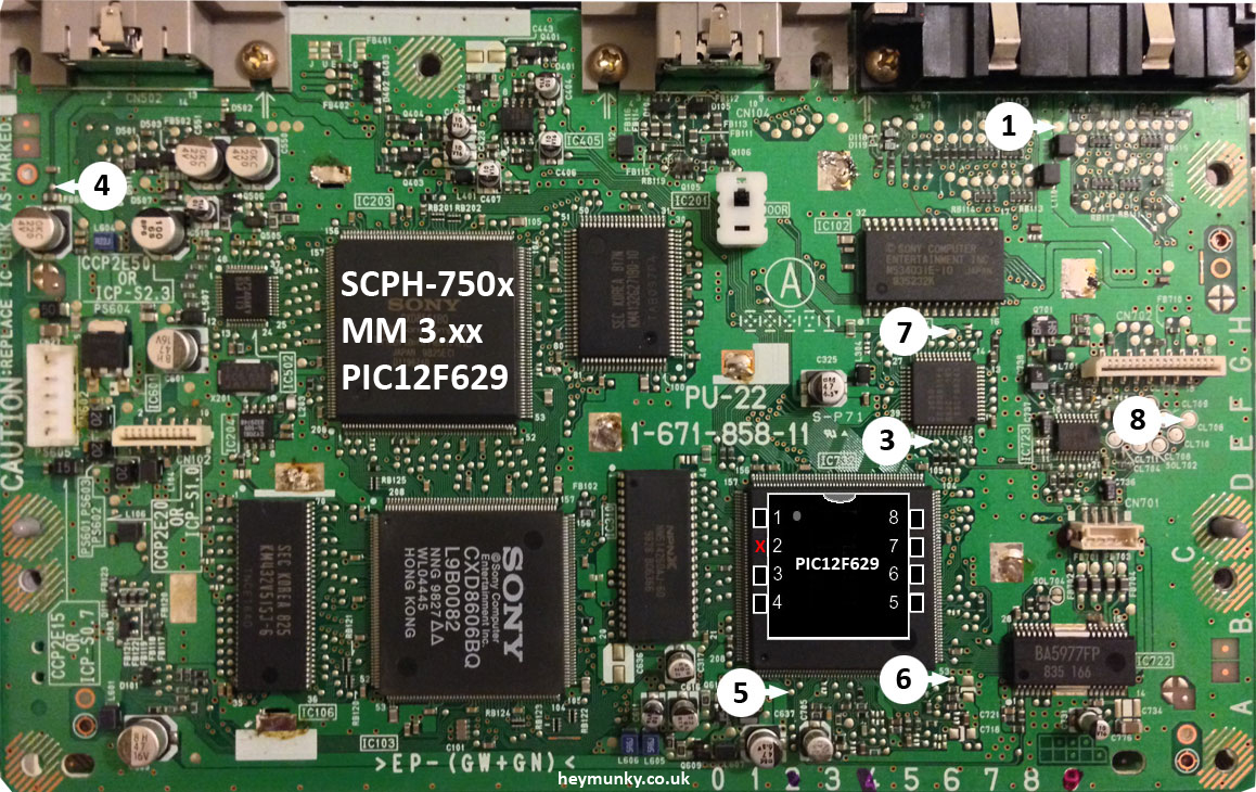