
Hi everyone!
I found this community, and I think I can get help from you.
I bought a dual PSX to USB adapter to use the PSX gamepad with my PC. It's a LINQ model
http://thumbs.ebaystatic.com/d/l225/m/m ... cJx-wA.jpg
It works quite well:
- I can play with a single gamepad with analog control
- I can play with 2 gamepads without analog control, or at least with just one using analog control; when one analog controller is on, one can't turn on the other (the second controller analog led turns on for few moments, than off again; or, the second one turns on, forcing the first one to turn off)
- rumble works, but when the motor runs, analog turns off
My guess is that there is some kind of current limitations. When a gamepad drains too much current, "something" happens.
I don't thing it's due to the 500 mA limit of the USB port, but something managed by the adapter.
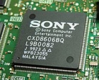
The adapter mount a chip and just a couple of resistors/capacitors. I can attach some images if it's useful.
Is there anyone else that experienced this behavior with similar adapters?
Does anyone have some hints about what's happanening? And maybe how to fix these issues? Or some other test to suggest to better find the problem?
Thanks to anyone!
Hack PSX-USB dual adapter due to max current limitations
-
carlo.vanoni
- Curious PSXDEV User

- Posts: 16
- Joined: Sep 15, 2014
-
carlo.vanoni
- Curious PSXDEV User
- Posts: 16
- Joined: Sep 15, 2014
UPDATE:
I've desolded the two controller motors, so no vibration is possible, and no currend will be drained when a rumble is requested. By the way, the analog will still deactivate when a rumble is supposed to occur.
So, it seems more like an in/out mess of the adapter. And maybe related to the above second problem (can't switch on both analog controller).
Any idea? Crappy chip firmware or crappy connections?
-
Shadow
 Verified
 - Admin / PSXDEV

- Posts: 2670
- Joined: Dec 31, 2012
- PlayStation Model: H2000/5502
- Discord: Shadow^PSXDEV
Overall crappy quality. It's better to build your own.
Development Console: SCPH-5502 with 8MB RAM, MM3 Modchip, PAL 60 Colour Modification (for NTSC), PSIO Switch Board, DB-9 breakout headers for both RGB and Serial output and an Xplorer with CAETLA 0.34.
PlayStation Development PC: Windows 98 SE, Pentium 3 at 400MHz, 128MB SDRAM, DTL-H2000, DTL-H2010, DTL-H201A, DTL-S2020 (with 4GB SCSI-2 HDD), 21" Sony G420, CD-R burner, 3.25" and 5.25" Floppy Diskette Drives, ZIP 100 Diskette Drive and an IBM Model M keyboard.
PlayStation Development PC: Windows 98 SE, Pentium 3 at 400MHz, 128MB SDRAM, DTL-H2000, DTL-H2010, DTL-H201A, DTL-S2020 (with 4GB SCSI-2 HDD), 21" Sony G420, CD-R burner, 3.25" and 5.25" Floppy Diskette Drives, ZIP 100 Diskette Drive and an IBM Model M keyboard.
-
carlo.vanoni
- Curious PSXDEV User
- Posts: 16
- Joined: Sep 15, 2014
I've bought a second one (it's quite cheap). I'll see if I get something better. Otherwise, I will use the connectors to build something custom. I've seen some guides here and there.
Does anyone have some suggestions about it?
I've seen an Arduino PSX library too. Maybe I'll do a preliminary test with it.
Also, since I will use the controllers with PC, and maaaaany games support well the x360 controller (and sometimes zero-support for different ones), it could be an idea to output x360 commands from the adapter. What do you think about it?
EDIT:
I found this
Does anyone have any info? The board is called USBJoy. I can't find any info...
EDIT 2:
Nope, the Arduino library is for controlling the Arduino, not to output the command to PC.
-
Shadow Verified
- Admin / PSXDEV
- Posts: 2670
- Joined: Dec 31, 2012
- PlayStation Model: H2000/5502
- Discord: Shadow^PSXDEV
The cheapest and easiest is to just buy an Arduino Leonardo and program it to output keyboard presses.
I did that for my Mega Drive controller.

I did that for my Mega Drive controller.
You do not have the required permissions to view the files attached to this post.
Development Console: SCPH-5502 with 8MB RAM, MM3 Modchip, PAL 60 Colour Modification (for NTSC), PSIO Switch Board, DB-9 breakout headers for both RGB and Serial output and an Xplorer with CAETLA 0.34.
PlayStation Development PC: Windows 98 SE, Pentium 3 at 400MHz, 128MB SDRAM, DTL-H2000, DTL-H2010, DTL-H201A, DTL-S2020 (with 4GB SCSI-2 HDD), 21" Sony G420, CD-R burner, 3.25" and 5.25" Floppy Diskette Drives, ZIP 100 Diskette Drive and an IBM Model M keyboard.
PlayStation Development PC: Windows 98 SE, Pentium 3 at 400MHz, 128MB SDRAM, DTL-H2000, DTL-H2010, DTL-H201A, DTL-S2020 (with 4GB SCSI-2 HDD), 21" Sony G420, CD-R burner, 3.25" and 5.25" Floppy Diskette Drives, ZIP 100 Diskette Drive and an IBM Model M keyboard.
-
carlo.vanoni
- Curious PSXDEV User
- Posts: 16
- Joined: Sep 15, 2014
In this way it's not possible to use analog controls or have rumble function.
-
Shadow Verified
- Admin / PSXDEV
- Posts: 2670
- Joined: Dec 31, 2012
- PlayStation Model: H2000/5502
- Discord: Shadow^PSXDEV
Ah, sorry, I forgot you wanted to use analog with DUAL-SHOCK support.
Anyhow, here is the USBJoy website: https://web.archive.org/web/20130427053 ... /08/usbjoy
The circuit will need a DC-DC converter circuit added in to boost the 5V to 7.5V.
If not, you can always use a 9V battery or a direct 9V DC line from a wall adapter (regulated down to 7V5 of course).
I also suggest you check out http://www.raphnet-tech.com/products.php
There are SMD PSX female controller connectors that you could use if you ever need them.
Development Console: SCPH-5502 with 8MB RAM, MM3 Modchip, PAL 60 Colour Modification (for NTSC), PSIO Switch Board, DB-9 breakout headers for both RGB and Serial output and an Xplorer with CAETLA 0.34.
PlayStation Development PC: Windows 98 SE, Pentium 3 at 400MHz, 128MB SDRAM, DTL-H2000, DTL-H2010, DTL-H201A, DTL-S2020 (with 4GB SCSI-2 HDD), 21" Sony G420, CD-R burner, 3.25" and 5.25" Floppy Diskette Drives, ZIP 100 Diskette Drive and an IBM Model M keyboard.
PlayStation Development PC: Windows 98 SE, Pentium 3 at 400MHz, 128MB SDRAM, DTL-H2000, DTL-H2010, DTL-H201A, DTL-S2020 (with 4GB SCSI-2 HDD), 21" Sony G420, CD-R burner, 3.25" and 5.25" Floppy Diskette Drives, ZIP 100 Diskette Drive and an IBM Model M keyboard.
-
carlo.vanoni
- Curious PSXDEV User
- Posts: 16
- Joined: Sep 15, 2014
WHOA! Kudos for you!
I will study the project carefully and than share my thoughts (carefully == no update for a while...).
About the female connector, I will use the crappy adapter one.
Also, I've read this comment in the page
"The thing is sony requires a 3.5V power, and the USBJoy provides 5V, this is not a problem to most no-names controllers, but the sony ones may not work."
I'm using my adapter with a sony and a no-name controller.
The "doubel analog" problem, indeed, affect the sony controller. In detail, this is what happens
1) sony analog on, no-name off
2) turn on no-name analog
3) no-name analog turns on, sony analog automatically turns off (it's always the sony analog that turns off!)
Didn't check the no-name rumble. WIll test this evening.
EDIT:
If it turns out that the 5V vs 3.5V issue might be the problem, I can use these approaches to change the input voltage of the controller:
1) a voltage divider with 2 resistor (simpler solution)
2) use a series diode to reduce the voltage (hints about the diode? An 1.2V diode will still be ok?)
3) use a 5V->3.3V voltage regulator (most "expensive" way)
What's your hint?
EDIT 2:
Here
http://pinouts.ru/Game/playstation_9_pinout.shtml
is stated that the dual shock pin uses 7.6V. So, maybe there is also some voltage/current problems to drive the dual shock motors. By the way, they actually works. Is it possible that, with 5V, they will just spin slower? I think that there is some kind of PWM (from the PlayStation or from the controller circuitry?) that let the motor spin slower/faster. If the power supply of this PWM is 5V instead of 7.6V, the maximum rotation speed will be a little less than the original; by the way, it still spins.
What you think about this?
-
carlo.vanoni
- Curious PSXDEV User
- Posts: 16
- Joined: Sep 15, 2014
UPDATE:
Non-Sony controller works well with the adapter. Dual shock works without analog disconnection. Looks even more like a 5V problem. I will do some measurements and check what's happening, and if needed I will install a voltage regulator (or similar) and see if the Sony controller starts working.
EDIT:
Uhm...
The Dual Shock power is, as expected, 5V. It is directly connected to the USB 5V.
The VCC pin is 0 when the controller is disconnected. With the controller, well, it's quite unstable. With just the controller is ~3.6V. When the analog is on is ~3.2V. With two controller and one analog (can't turn on both) is ~3.1V.
Is it possible that the unstable VCC cause these problems?
I will search for a spare voltage regulator and test if something changes.
Also, I have to check where to connect it; my first thought was that the 5V from USB are directly connected to VCC, so it was quite easy to connect the regulator. Sinche there is already some sort of regulator, I have to understand what's happening.
-
Shadow Verified
- Admin / PSXDEV
- Posts: 2670
- Joined: Dec 31, 2012
- PlayStation Model: H2000/5502
- Discord: Shadow^PSXDEV
I have gotten PS2 controllers to work off of 5V too, but they perform subpar. If your research is correct, my assumption would be that Sony sends 7V5 down the line and regulates it to 5V to compensate for the resistance losses along the cable. Use a voltage regulator since it will provide a much cleaner DC output, be more efficient and support higher loads. This makes the most sense since MCU's do not run at 7V5 but instead 5V or 3V3, but then again they could be driving the motors using 7.5V since they are generally rated for 6V using some discrete transistor gating and diodes and or resistors to drop the extra volt and a half.
Allinall, just feed it 7.5 volts from a greater than 9 volt supply via a proper regulated circuit
Allinall, just feed it 7.5 volts from a greater than 9 volt supply via a proper regulated circuit
Development Console: SCPH-5502 with 8MB RAM, MM3 Modchip, PAL 60 Colour Modification (for NTSC), PSIO Switch Board, DB-9 breakout headers for both RGB and Serial output and an Xplorer with CAETLA 0.34.
PlayStation Development PC: Windows 98 SE, Pentium 3 at 400MHz, 128MB SDRAM, DTL-H2000, DTL-H2010, DTL-H201A, DTL-S2020 (with 4GB SCSI-2 HDD), 21" Sony G420, CD-R burner, 3.25" and 5.25" Floppy Diskette Drives, ZIP 100 Diskette Drive and an IBM Model M keyboard.
PlayStation Development PC: Windows 98 SE, Pentium 3 at 400MHz, 128MB SDRAM, DTL-H2000, DTL-H2010, DTL-H201A, DTL-S2020 (with 4GB SCSI-2 HDD), 21" Sony G420, CD-R burner, 3.25" and 5.25" Floppy Diskette Drives, ZIP 100 Diskette Drive and an IBM Model M keyboard.
-
carlo.vanoni
- Curious PSXDEV User
- Posts: 16
- Joined: Sep 15, 2014
The 7V5 vs 5V is not a real problem for me. It really seems that the motors work correctly with a 5V supply, too.
About the 5V vs 3V3 problem, that is the real issue (gamepad basic functions not working properly), I looked closely to the board to understand what's going on (no schematic available, so I have to look at the PCB). It looks that the VCC pins of the two connectors are connected together, and this is ok. Following the path, it leads to.... nothing. Odd! The path terminates on a there-is-supposed-to-be-a-diode symbol, but there is no diode. The diode will connect the USB 5V pin with the VCC; I suppose the idea is to subtract the diode forward voltage from USB 5V (one of the options I've listed above).
I tried to connect a 1N4001 (not soldered at the moment), that has a 1V forward voltage and can support 1A current for the load. Well, from a quick test, the issue seems resolved! I can turn on both gamepad analog control. The vibration request (didn't test the actual vibration, since I've desoldered the motors pins...) doesn't turn off the analog switch on the Sony controller.
I will make further tests. Also, I will take a couple of photos of the PCB as-is and with the hacked version (mounted diode).
I suppose that a voltage regulator will be even better than the diode, but I have no spare LM3940 on my hand at the moment. Maybe I will test it in the future with the second adapter.
-
Shadow Verified
- Admin / PSXDEV
- Posts: 2670
- Joined: Dec 31, 2012
- PlayStation Model: H2000/5502
- Discord: Shadow^PSXDEV
Interesting. They probably realised that since USB can only support up to 500mAh they better leave it out.
As I stated, mine did work at 5V and it will drive the motors, but they won't be at their full potential. It also means more current will be required, though, that depends if I was right or not about the 7V5 to 6V conversion for the motors. If you're going to be using two DUAL-SHOCK controllers off of a single USB port, use USB 3.0 since it can supply 1A. Otherwise, your USB port may disable itself or if it's really cheap, let out the magic smoke.
As I stated, mine did work at 5V and it will drive the motors, but they won't be at their full potential. It also means more current will be required, though, that depends if I was right or not about the 7V5 to 6V conversion for the motors. If you're going to be using two DUAL-SHOCK controllers off of a single USB port, use USB 3.0 since it can supply 1A. Otherwise, your USB port may disable itself or if it's really cheap, let out the magic smoke.
Development Console: SCPH-5502 with 8MB RAM, MM3 Modchip, PAL 60 Colour Modification (for NTSC), PSIO Switch Board, DB-9 breakout headers for both RGB and Serial output and an Xplorer with CAETLA 0.34.
PlayStation Development PC: Windows 98 SE, Pentium 3 at 400MHz, 128MB SDRAM, DTL-H2000, DTL-H2010, DTL-H201A, DTL-S2020 (with 4GB SCSI-2 HDD), 21" Sony G420, CD-R burner, 3.25" and 5.25" Floppy Diskette Drives, ZIP 100 Diskette Drive and an IBM Model M keyboard.
PlayStation Development PC: Windows 98 SE, Pentium 3 at 400MHz, 128MB SDRAM, DTL-H2000, DTL-H2010, DTL-H201A, DTL-S2020 (with 4GB SCSI-2 HDD), 21" Sony G420, CD-R burner, 3.25" and 5.25" Floppy Diskette Drives, ZIP 100 Diskette Drive and an IBM Model M keyboard.
-
carlo.vanoni
- Curious PSXDEV User
- Posts: 16
- Joined: Sep 15, 2014
Yay magic smoke! 
Well, another idea could be to use another diode to limit the current to the dual shock power pin. This will furthermore decrease the input voltage, but again, it's not a problem for me. Noob question: if I put 3 diodes in parallel, each one with 1V forward voltage and 100mA output current:
- do I still get 5V-1V=4V power to the motor pin? (I think so)
- does the maximum curren be limited to 100mAx3 = 300mA? (I can prevent USB problems this way)
About your controller, driven at 5V with the adapter (to be sure, I'm talking about the VCC voltage supply here, not the motors), is it an original Sony controller?
-
Shadow Verified
- Admin / PSXDEV
- Posts: 2670
- Joined: Dec 31, 2012
- PlayStation Model: H2000/5502
- Discord: Shadow^PSXDEV
If you put the diodes in parallel, yes they will accept the load somewhat equally, but it is not wise.carlo.vanoni wrote:Yay magic smoke!
Well, another idea could be to use another diode to limit the current to the dual shock power pin. This will furthermore decrease the input voltage, but again, it's not a problem for me. Noob question: if I put 3 diodes in parallel, each one with 1V forward voltage and 100mA output current:
- do I still get 5V-1V=4V power to the motor pin? (I think so)
- does the maximum curren be limited to 100mAx3 = 300mA? (I can prevent USB problems this way)
About your controller, driven at 5V with the adapter (to be sure, I'm talking about the VCC voltage supply here, not the motors), is it an original Sony controller?
Diodes in parallel heat up their resistance decreases. This then ends up making the diode take on more current than the others which makes it heat up more. If one goes open, you're in bigger trouble.
I would not do it. It's better to just use a larger diode that can accept more wattage. Otherwise, install a fuse.
Yes, my controller was an official Sony PlayStation 2 controller.
Development Console: SCPH-5502 with 8MB RAM, MM3 Modchip, PAL 60 Colour Modification (for NTSC), PSIO Switch Board, DB-9 breakout headers for both RGB and Serial output and an Xplorer with CAETLA 0.34.
PlayStation Development PC: Windows 98 SE, Pentium 3 at 400MHz, 128MB SDRAM, DTL-H2000, DTL-H2010, DTL-H201A, DTL-S2020 (with 4GB SCSI-2 HDD), 21" Sony G420, CD-R burner, 3.25" and 5.25" Floppy Diskette Drives, ZIP 100 Diskette Drive and an IBM Model M keyboard.
PlayStation Development PC: Windows 98 SE, Pentium 3 at 400MHz, 128MB SDRAM, DTL-H2000, DTL-H2010, DTL-H201A, DTL-S2020 (with 4GB SCSI-2 HDD), 21" Sony G420, CD-R burner, 3.25" and 5.25" Floppy Diskette Drives, ZIP 100 Diskette Drive and an IBM Model M keyboard.
-
carlo.vanoni
- Curious PSXDEV User
- Posts: 16
- Joined: Sep 15, 2014
Well, that's awkward...
I've installed the diode. Now the Sony controller works well, like in the test; dual shock is ok, analog control can be used simultaneously with analog of non-sony controller.
BUT! Dual shock of non-sony controller doesn't work anymore... What happes is different from the previous Sony problem, where a "shock" request switched off the analog control. Here there's simply no motor spin, but the analog control remains on.
...????
-
Shadow Verified
- Admin / PSXDEV
- Posts: 2670
- Joined: Dec 31, 2012
- PlayStation Model: H2000/5502
- Discord: Shadow^PSXDEV
The third party (non Sony) controller may require the seven and a half volts instead of the five.
Development Console: SCPH-5502 with 8MB RAM, MM3 Modchip, PAL 60 Colour Modification (for NTSC), PSIO Switch Board, DB-9 breakout headers for both RGB and Serial output and an Xplorer with CAETLA 0.34.
PlayStation Development PC: Windows 98 SE, Pentium 3 at 400MHz, 128MB SDRAM, DTL-H2000, DTL-H2010, DTL-H201A, DTL-S2020 (with 4GB SCSI-2 HDD), 21" Sony G420, CD-R burner, 3.25" and 5.25" Floppy Diskette Drives, ZIP 100 Diskette Drive and an IBM Model M keyboard.
PlayStation Development PC: Windows 98 SE, Pentium 3 at 400MHz, 128MB SDRAM, DTL-H2000, DTL-H2010, DTL-H201A, DTL-S2020 (with 4GB SCSI-2 HDD), 21" Sony G420, CD-R burner, 3.25" and 5.25" Floppy Diskette Drives, ZIP 100 Diskette Drive and an IBM Model M keyboard.
-
carlo.vanoni
- Curious PSXDEV User
- Posts: 16
- Joined: Sep 15, 2014
Well, but it worked before connecting the diode. Also, the diode scales the voltage of the VCC pin. The Dual Shock voltage is still directly connected to the USB 5V.
I'll do some more measurements.
I'll do some more measurements.
-
carlo.vanoni
- Curious PSXDEV User
- Posts: 16
- Joined: Sep 15, 2014
Dunno...
Moros voltage is 5V (shorted with USB 5V). Gamepad Vcc with diode is between 4.3V and 4.5V. Without the diode it was around 5V.
Here are the images I took.
First two images are the adapter bottom/top before the hack (wow! look at those weld joint!).
In the bottom one you can see the Vcc path (yellow). It connects the two connectors' Vcc, than the path continues in the top layer, than again on the bottom to the "supposed" diode pin. On the other side, the pin is connected to USB 5V. Soooo, Vcc is floating. ....wtf? I still measure around 5V when the diode is unconnected.


After connecting the diode, these is a connection between Vcc and USB 5V (actually, my multimeter measures 5.2V). Vcc becomes 4.3V (vary +-0.1V with one or two gamepad connected).

Any idea about what's happening? Do you think it's possible that Vcc is floating?
As said, I've "visually" followed the path from Vcc pins to the diode pins (yellow path on the images). Carfully looked for other paths, but didn't noticed any. Also, checked for shorts between Vcc and other points on the PCB, but I found none. So I'm quite sure Vcc is actually floating.
Awfully, I think my new adapter was lost around Italy (damn mail service...), so at the moment I can't made further test with the original version. Well, I can actually remove the diode.... but I'm lazy.
Moros voltage is 5V (shorted with USB 5V). Gamepad Vcc with diode is between 4.3V and 4.5V. Without the diode it was around 5V.
Here are the images I took.
First two images are the adapter bottom/top before the hack (wow! look at those weld joint!).
In the bottom one you can see the Vcc path (yellow). It connects the two connectors' Vcc, than the path continues in the top layer, than again on the bottom to the "supposed" diode pin. On the other side, the pin is connected to USB 5V. Soooo, Vcc is floating. ....wtf? I still measure around 5V when the diode is unconnected.
After connecting the diode, these is a connection between Vcc and USB 5V (actually, my multimeter measures 5.2V). Vcc becomes 4.3V (vary +-0.1V with one or two gamepad connected).
Any idea about what's happening? Do you think it's possible that Vcc is floating?
As said, I've "visually" followed the path from Vcc pins to the diode pins (yellow path on the images). Carfully looked for other paths, but didn't noticed any. Also, checked for shorts between Vcc and other points on the PCB, but I found none. So I'm quite sure Vcc is actually floating.
Awfully, I think my new adapter was lost around Italy (damn mail service...), so at the moment I can't made further test with the original version. Well, I can actually remove the diode.... but I'm lazy.
You do not have the required permissions to view the files attached to this post.
-
carlo.vanoni
- Curious PSXDEV User
- Posts: 16
- Joined: Sep 15, 2014
I can almost confirm that, originally, the Vcc pins was floating. I've desoldered the Vcc pin of one connector, and the controller still works.
My idea was to have a connector using the Vcc after the diode (for Sony controller), and the other one floating, like in the "original state" (for the non-Sony controller). Btw, the non-Sony controller still doesn't vibrate, while buttons and analog controls work like a charm, even if no Vcc is provided to the controller (WTF!!!)
My idea was to have a connector using the Vcc after the diode (for Sony controller), and the other one floating, like in the "original state" (for the non-Sony controller). Btw, the non-Sony controller still doesn't vibrate, while buttons and analog controls work like a charm, even if no Vcc is provided to the controller (WTF!!!)
-
Shendo
 Verified
 - C Programming Expert

- Posts: 250
- Joined: Mar 21, 2012
- I am a: Programmer
- Motto: Never settle
- PlayStation Model: SCPH-7502
- Discord: ShendoXT
- Location: Croatia, EU
Don't forget that connector has two vcc pins, a 3.3 V one and 7.6 one.
That's probably why your controller works but it has no rumble.
That's probably why your controller works but it has no rumble.
Dev console: SCPH-7502, FreePSXBoot, CH340 serial cable.
Who is online
Users browsing this forum: No registered users and 4 guests
 , "PlayStation",
  ,
,  , "DUALSHOCK", "Net Yaroze" and "PSone" are registered trademarks of Sony Computer Entertainment Inc.