
SIOCONS compatible USB Cable
-
Greg
 Verified
 - Serious PSXDEV User

- Posts: 101
- Joined: Sep 09, 2013
- PlayStation Model: SCPH-7501
- Location: Port-au-Prince, HAITI
The PSX serial cable has been made to be connected betwen 2 PSX, that mean TXD pin from PSX number 1 go to RXD PSX number 2 and so for the 3 other pins. When you cut the cable in half, you will always have a mismatch. 
1 x SCPH-7501, 2 x SCPH-7001, 2 x SCPH-5501
1 x Pro Action Replay with "Dual Rom Mod", ROM 1: Caetla, ROM 2: UNIROM
1 x Xplorer V2 with Caetla
1 x GameShark V2.1
1 x GameShark Pro V3.0
1 x CommLinkUSB
1 x XLinkUSB
1 x Pro Action Replay with "Dual Rom Mod", ROM 1: Caetla, ROM 2: UNIROM
1 x Xplorer V2 with Caetla
1 x GameShark V2.1
1 x GameShark Pro V3.0
1 x CommLinkUSB
1 x XLinkUSB
-
gwald
 Verified
 - Net Yaroze Enthusiast

- Posts: 289
- Joined: Sep 18, 2013
- I am a: programmer/DBA
- PlayStation Model: Net Yaroze
- Contact:
Well, I finished it and it was a success! 

I used the sticker/old end
So I used Dan's table with the correct colours:
PSX Sticker/old end
1 – green .....-> CTS
2 – purple ....-> GND
3 – orange....-> DSR
4 – grey .......-> RTS
5 – brown .....-> RXD
6 – blue ........-> DTR
7 – red-NA
8 – yellow ....-> TXD
I started with my very old soldering ion but it made a mess!

I bought a new, cheap one (60watts) and solder, cleaned up the board and it was way easier and better!
It probably looks really bad to the pros here, but this is the smallest soldering I've done and it worked, so


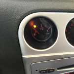
Testing, the RX/RT lights come on, pretty cool!

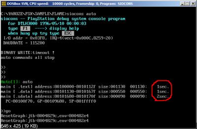
And siocons!
Sending:

Go:

And running:

USB Net Yaroze cable


A further tip, Linux non root requires access rights to /dev/ttyUSB0.
ie: sudo adduser ?user? dialout
Then log out to apply the changes, chmod or chown /dev/ttyUSB0 wont hold for the next reboot.
More images here, I still got the 'good' end so I'll probably do it again some other time, it was a nice project!
The cable is also capable of being used with SERIALPSX, which is pretty, just re apply the command in first post to reverse the initial reversing, etc.
Looking at also using this cable with PSXSDK/blade
Thanks again to danhans42 for his great tutorial and help along the way, no way could I have done it by myself
I used the sticker/old end
So I used Dan's table with the correct colours:
PSX Sticker/old end
1 – green .....-> CTS
2 – purple ....-> GND
3 – orange....-> DSR
4 – grey .......-> RTS
5 – brown .....-> RXD
6 – blue ........-> DTR
7 – red-NA
8 – yellow ....-> TXD
I started with my very old soldering ion but it made a mess!
I bought a new, cheap one (60watts) and solder, cleaned up the board and it was way easier and better!
It probably looks really bad to the pros here, but this is the smallest soldering I've done and it worked, so
Testing, the RX/RT lights come on, pretty cool!
And siocons!
Sending:
Go:
And running:
USB Net Yaroze cable
Cool, I knew it was a null modem with cables crossed, but didn't know details
A further tip, Linux non root requires access rights to /dev/ttyUSB0.
ie: sudo adduser ?user? dialout
Then log out to apply the changes, chmod or chown /dev/ttyUSB0 wont hold for the next reboot.
More images here, I still got the 'good' end so I'll probably do it again some other time, it was a nice project!
The cable is also capable of being used with SERIALPSX, which is pretty, just re apply the command in first post to reverse the initial reversing, etc.
Looking at also using this cable with PSXSDK/blade
Thanks again to danhans42 for his great tutorial and help along the way, no way could I have done it by myself

No worries, glad you got it working.
Just to add, you don't need to do anything to use psxserial or anything else, just use as is as it works for everything. No need to reprogram the ftdi with ftdi-prog or whatever.
Just to add, you don't need to do anything to use psxserial or anything else, just use as is as it works for everything. No need to reprogram the ftdi with ftdi-prog or whatever.
danhans42. Are you still making versions of this for sale?
These sorts of cables look a nice option now
Standard pinout: 1 = CTS 2 = DSR 3 = RX 4 = Ground 5 = Ground 6 = TX 7 = DTR 8 = RTS
No if we just stick a RJ45 socket on the PSX NIce.
These sorts of cables look a nice option now
Standard pinout: 1 = CTS 2 = DSR 3 = RX 4 = Ground 5 = Ground 6 = TX 7 = DTR 8 = RTS
No if we just stick a RJ45 socket on the PSX
-
Shendo
 Verified
 - C Programming Expert

- Posts: 250
- Joined: Mar 21, 2012
- I am a: Programmer
- Motto: Never settle
- PlayStation Model: SCPH-7502
- Discord: ShendoXT
- Location: Croatia, EU
I believe those are RS232 cables and not TTL. I remember from my high school days
in Cisco course we used cables with DB9 to RJ45 connectors which those cables you linked are emulating.
In short, you will fry your PS1 if you connect it without MAX232 IC.
Edit:
Haha, I still have one of those lying around.
in Cisco course we used cables with DB9 to RJ45 connectors which those cables you linked are emulating.
In short, you will fry your PS1 if you connect it without MAX232 IC.
Edit:
Haha, I still have one of those lying around.
You do not have the required permissions to view the files attached to this post.
Dev console: SCPH-7502, FreePSXBoot, CH340 serial cable.
You need a GENUINE FTDI module, the one used by gwald is currently the best solution and is easily availble. There are not many around that have the full handshaking, as most applications (Arduino etc) its not needed. It must have all the signals detailed in my initial post (RXD/TXD/RTS/CTS/DTR/DSR) - if not you are s**t outta luck.
I would be seriously surprised if you would ever find a fully wired cable that would have all these signals.
I would be seriously surprised if you would ever find a fully wired cable that would have all these signals.
nah i think what you have is differentShendo wrote: ↑November 24th, 2018, 12:50 pm I believe those are RS232 cables and not TTL. I remember from my high school days
in Cisco course we used cables with DB9 to RJ45 connectors which those cables you linked are emulating.
In short, you will fry your PS1 if you connect it without MAX232 IC.
Edit:
Haha, I still have one of those lying around.
cisco_cable.png
This is a USB to RJ45 with the following pin outs
based on this chip
https://www.ftdichip.com/Support/Docume ... FT232R.pdf
Seems like the right stuff?
Max Baud Rate: 921.6 Kbps Data Bits 7, 8 FIFO 256 Bytes Parity: None, Odd, Even, Mark, Space Stop Bits: 1, 2 Support Android,
Support Win 8, Win 7, XP, 2000, Linix, Mac OS Integrated 1024 byte EEPROM,
support Vendor ID re-write,
support Mprog3.5 Support FTDI VCP driver and D2XX drive
Standard pinout: 1 = CTS 2 = DSR 3 = RX 4 = Ground 5 = Ground 6 = TX 7 = DTR 8 = RTS
28AWG*8C, copper, , 2m as standard length Self-powered from usb directly, no extra power needed.
Operating system support
danhans42 wrote: ↑November 25th, 2018, 3:23 am You need a GENUINE FTDI module, the one used by gwald is currently the best solution and is easily availble. There are not many around that have the full handshaking, as most applications (Arduino etc) its not needed. It must have all the signals detailed in my initial post (RXD/TXD/RTS/CTS/DTR/DSR) - if not you are s**t outta luck.
I would be seriously surprised if you would ever find a fully wired cable that would have all these signals.
Quoted as genuine
Seems to have the pins
Standard pinout: 1 = CTS 2 = DSR 3 = RX 4 = Ground 5 = Ground 6 = TX 7 = DTR 8 = RTS
-
Shendo Verified
- C Programming Expert
- Posts: 250
- Joined: Mar 21, 2012
- I am a: Programmer
- Motto: Never settle
- PlayStation Model: SCPH-7502
- Discord: ShendoXT
- Location: Croatia, EU
Yes, that cable has FTDI chip but also a ZT213 which converts TTL signals given by the FTDI to RS232.
If you were to remove ZT213 or add MAX232 then yes, you can use the cable. Otherwise no.
Just check out the name of that cable:
opposed to 0V to 3.3V TTL used on a PS1.
--
Genuine FTDI is only needed if you want to invert handshaking lines without using extra components.
You can use any USB-TTL module provided it has broken out pins and simply make an inverter using NPN transistors and resistors.
If you were to remove ZT213 or add MAX232 then yes, you can use the cable. Otherwise no.
Just check out the name of that cable:
You have all the needed pins but RS232 uses -25V to +25V for signaling,YIDAMA-TONGLE for Win 8, Win 10, Android, Mac, FT232+ZT213, USB to RJ45 RS232 console cable.
opposed to 0V to 3.3V TTL used on a PS1.
--
Genuine FTDI is only needed if you want to invert handshaking lines without using extra components.
You can use any USB-TTL module provided it has broken out pins and simply make an inverter using NPN transistors and resistors.
Dev console: SCPH-7502, FreePSXBoot, CH340 serial cable.
You can also shift the logic voltage using 74hc00 - with that solution you can partially follow the original guide from hitmen to build a siocons cable - you just omit the MAX232 and replace with any USB UART
I could write a separate guide for that if anyone is interested, as this one was intended to be just using an FTDI as it requires no extra parts other than a cable.
The cheapest solution is a - CH340 + 74HC00, it costs less than $1.80USD.. if anyone is interested I will write up a guide for that.
I will also start to add compatible modules into the first post.
Ill do a full guide shortly, but the simple diagram below is if you want to use non-FTDI or fake-FTDI modules :-
Just get hold of a 74HC00 and wire as above. I did briefly test this on a CP2103 and it worked perfectly.
Just get hold of a 74HC00 and wire as above. I did briefly test this on a CP2103 and it worked perfectly.
You do not have the required permissions to view the files attached to this post.


-
brill
 Verified
 - Active PSXDEV User

- Posts: 63
- Joined: Apr 30, 2013
- PlayStation Model: SCPH-7502
- Contact:
assembled the scheme, but modified it a little according to the previous scheme, since It seems to have errors

I also tried to change the chip to SN74HC04N

the result is the same as with 74HC00

load time is not impressive


Dev console: SCPH-7502 + Xplorer with custom MultiRom firmware
Dev PC: Windows 98 SE, Celeron at 633MHz, 128MB RAM, 20GB HDD
Dev PC: Windows 98 SE, Celeron at 633MHz, 128MB RAM, 20GB HDD
Load times are never going to be impressive, the speed is bottlenecked by the protocol used.
-
Xrider
 Verified
 - Curious PSXDEV User

- Posts: 31
- Joined: Jan 04, 2019
- I am a: Hardware Dev
- PlayStation Model: SCPH-5502
- Contact:
Hello,
i have make a tutorials for the beginner, it's available on my web site :
Delta Island : Serial to USB Net Yaroze tutorials
Enjoy
i have make a tutorials for the beginner, it's available on my web site :
Delta Island : Serial to USB Net Yaroze tutorials
Enjoy
Last edited by Xrider on March 10th, 2022, 6:11 am, edited 1 time in total.
-
brill Verified
- Active PSXDEV User
- Posts: 63
- Joined: Apr 30, 2013
- PlayStation Model: SCPH-7502
- Contact:
Xrider, this UART module did't work for me without inversion of the HANDSHAKE lines.
Here either add an additional chip (74XX), or change the FTDI chip to the original one.
Could you post your wiring diagram?
Thx
Here either add an additional chip (74XX), or change the FTDI chip to the original one.
Could you post your wiring diagram?
Thx
Dev console: SCPH-7502 + Xplorer with custom MultiRom firmware
Dev PC: Windows 98 SE, Celeron at 633MHz, 128MB RAM, 20GB HDD
Dev PC: Windows 98 SE, Celeron at 633MHz, 128MB RAM, 20GB HDD

-
brill Verified
- Active PSXDEV User
- Posts: 63
- Joined: Apr 30, 2013
- PlayStation Model: SCPH-7502
- Contact:
DeSoldered from the old motherboard SN74LS00N and now the speed has become normal.
P.S.: in the previous configuration SN74HC00N chip was installed
I hope this will be useful information for the following pioneers
Solution

P.S.: in the previous configuration SN74HC00N chip was installed
I hope this will be useful information for the following pioneers
Solution
You do not have the required permissions to view the files attached to this post.
Last edited by brill on January 28th, 2019, 12:03 pm, edited 1 time in total.
Dev console: SCPH-7502 + Xplorer with custom MultiRom firmware
Dev PC: Windows 98 SE, Celeron at 633MHz, 128MB RAM, 20GB HDD
Dev PC: Windows 98 SE, Celeron at 633MHz, 128MB RAM, 20GB HDD
Who is online
Users browsing this forum: No registered users and 4 guests
 , "PlayStation",
  ,
,  , "DUALSHOCK", "Net Yaroze" and "PSone" are registered trademarks of Sony Computer Entertainment Inc.