Very nice progess, Akari. I really love this project.
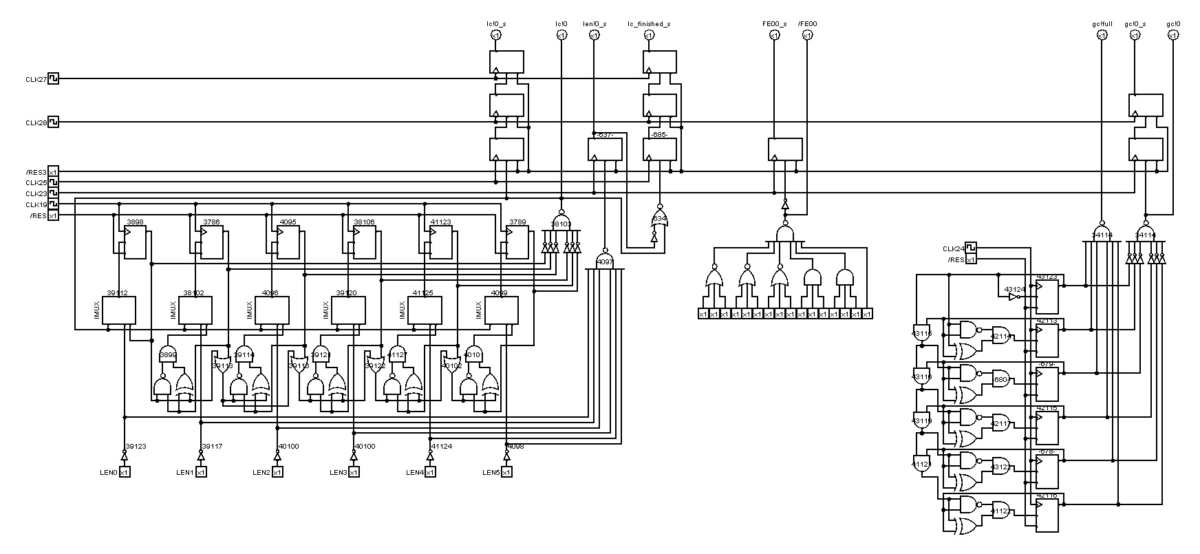
Anyway, I think that I now understand most of the RLE circuit, so let me report my findings, maybe it can be of help to everyone as well. I will refer to this
version of Akari's RLE circuit schematic that I structured into its components. Of course, my descriptions are tentative and may contain errors, so feel free to correct me!
The counters are mostly self-explanatory, so I will omit them here. At the bottom, we have the control circuit that outputs the clocks for most other components. It basically contains a finite state machine that implements a two-level pipeline: one that enters a new stage every 4 cycles (right shift register), and one that changes every cycle (left shift register), but repeats every 4 cycles. This is done so that the components can be orchestrated in a pipelined fashion, where each component can start in an arbitrary cycle and be pipelined either every 4 or every cycle. For example, the multipliers are clocked every master clock cycle but output the result only every four cycles to the next pipeline stage. This is because the multipliers need four adds to get the result, so every cycle an add must be executed, and every 4 cycles the product is ready. Whether the state machine enters the next state is controlled mostly by the counter flags (full, zero, etc.), but also by some other flags (e.g. data == 0xfe00).
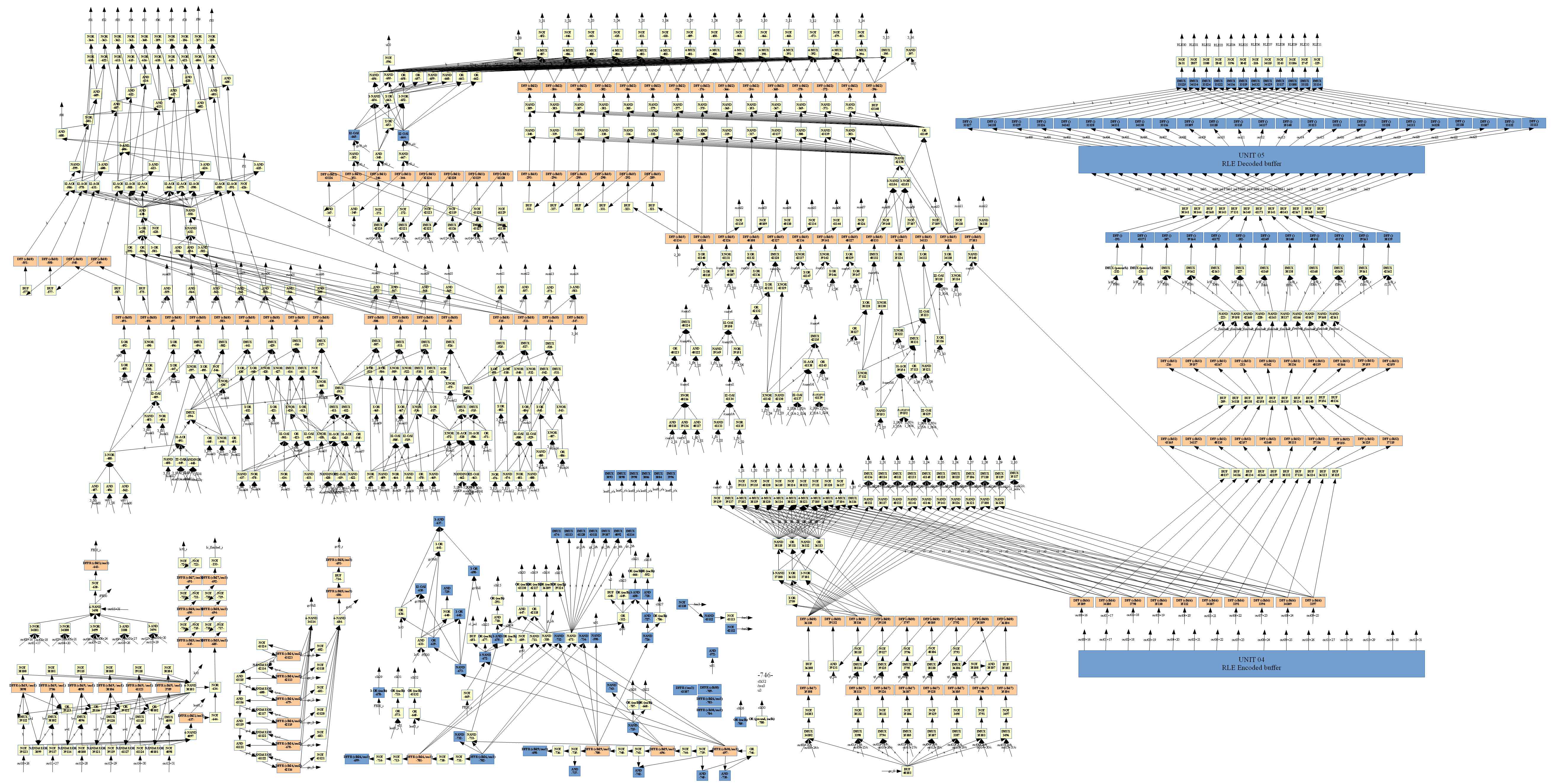
In the center of the schematic we have the quantization table multiplier that multiplies the data with the elements of the quantization table/matrix. I am fairly sure that this is a variant of the Booth multiplication algorithm where instead of bit slices of length 2, we look at bit slices of length 3. This particular multiplier works according to
this algorithm. I can elaborate if desired. (By the way, I noticed that the multiplier of the IDCT is exactly the same algorithm, just a different, more parallelized, hardware implementation). At the end, before the result is written to the next stage, the result is clamped to 15 bits (the multiplier itself calculates the the full 19=11+8 bits of the result).
Next is the quantization scale multiplier. It's again the same algorithm, but implemented a bit differently. Because every element of our block needs to be multiplied by QS, the shift register that selects the next 3-bit-slice is cyclic and repeats every 4 cycles. What I tagged as "constant factor" is actually the factor 8 that is used with the very first element (it's probably 8 in order to compensate for the division by 8 in the following steps). The result of the multiplication drops bits 0 and 1, which is equivalent to a right shift by 2, or an integer division by 4 (the last perceived division by 2 probably stems from the very last step, but I'm not too sure; additional input would from others would be appreciated).
Finally, the result is clamped to 12 bits, and then, as Akari mentioned, rounded to the next even number closer to zero (except -1, which stays the same). I do not know why this is done; does -1 have a special meaning? I am not too knowledgeable about JPEG compression. But I guess this is where the last perceived division by 2 comes from; it's not actually a division (that's why I wrote "perceived"), but the precision is effectively reduced by one bit.
So overall the steps should be:
1. res = clamp_to_15_bits(val * qt[k])
2. res = clamp_to_12_bits((res * qs) >> 2)
3. res = res == -1 ? -1 : round_to_even_number_closer_to_zero(res)
