Page 1 of 2
PSNee V8 - Ultimate PSX unlocker
Posted: August 16th, 2021, 9:03 pm
by postal2201
Hi guys! I want to share with you a new project of a chip mod.
The first stealth modchip supporting
unlocking BIOS of Japanese versions Sony PlayStation 1
This project was developed by
brill &
postal2201 (me

), based on PSNee V7 open source project.
http://www.emu-land.net/forum/index.php ... 934.0.html
Main features of PSNee V8:
1. Support for BIOS patching of Japanese consoles. Now you don't need to change the BIOS chip to hack Japanese consoles.
2. New type of BIOS patching for SCPH-102. Now the console BIOS does not switch to 60Hz on boot, so there should be no problem with portable LCD screens.
3. Auto region mod. The chip sends the SCEX code corresponding to your console model, unlocking is faster.
4. Ability to disable BIOS patching using a switch, without flashing the chip.
5. Refusal of all Arduino functions. The Arduino.h library is not used in the project.
PsNee V8 supports the following MCU's:
- ATmega328(A/P/PA) @16Mhz
- ATmega168(A/P/PA) @16Mhz
To install via the Arduino IDE may require the installation of the
MiniCore package.
https://github.com/MCUdude/MiniCore
Use the programmer to flash MCU. Flashing via COM port is not supported.
Don't use a bootloader!
Example of correct setting for ATmega328P:
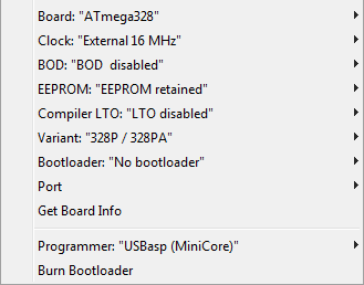
Before flashing the MCU, you need to configure the fuses.
- Fuses for
JAP_FAT consoles:
H: DF, L: EE, E: FF
- Fuses for
all other consoles:
H: DF, L: FF, E: FF
The division by model for JAP_FAT consoles, especially 5000 and earlier models, is rather arbitrary. When choosing a configuration in the .ino file, it is advisable to focus on the CRC BIOS of your console. To check the CRC, you can use the Bios Dumper attached in the attachment.
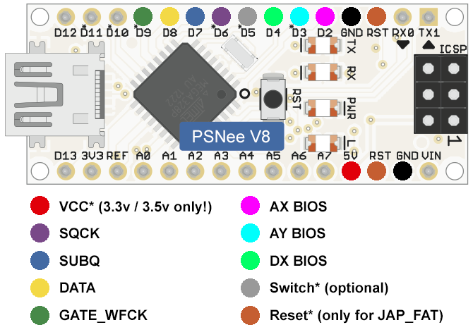
Installation diagram:
 https://github.com/postal2201/PSNee_V8
Re: PSNee V8 - Ultimate PSX unlocker
Posted: August 18th, 2021, 11:58 am
by L10N37
Good work on the chip!
I'm currently porting a new modchip across to PIC in ASM and just an idea I used to disable my modchip
Check the drive lid status on power on as oppose to installing an actual switch.
This way, you only need to boot the console with the lid open, then close it and you have removed the BIOS patch and can leave everything else active.
Saves drilling holes in the console or what not.
Re: PSNee V8 - Ultimate PSX unlocker
Posted: September 26th, 2021, 4:32 am
by zzymissyou
"Before flashing the MCU, you need to configure the fuses.",How?
I'm not do this,and PSNee V8(my arduino nano)is also do well in my scph-7000(pu-20 board).
Re: PSNee V8 - Ultimate PSX unlocker
Posted: October 4th, 2021, 4:56 pm
by postal2201
zzymissyou wrote: September 26th, 2021, 4:32 am
"Before flashing the MCU, you need to configure the fuses.",How?
I'm not do this,and PSNee V8(my arduino nano)is also do well in my scph-7000(pu-20 board).
Will work until you press the reset button on the console. Flashing fuses is needed for correct operation of reset on Japanese BIOS.
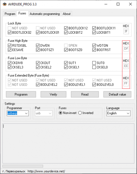
You can flash fuses using avrdude prog.

On the picture fuses for JAP_FAT consoles in avrdude prog (High: DF, Low: EE, Extended: FF)
Re: PSNee V8 - Ultimate PSX unlocker
Posted: December 3rd, 2021, 5:33 am
by leafy
Great! Which programmer did you use to flash? I got a chip flashed using the AVR Pocket Programmer with the miniCore loaded into the Arduino IDE. I used a solderless breadboard with ATmega328P in DIP format to ICSP.
I think it is important to note that your circuit assumes using an external 16MHz clock source, which you would get with say the Arduino Nano. However, a factory default chip doesn't come programmed with these fuse settings, and you need to add a 16MHz crystal or resonator, with the appropriate capacitors. I used a ceramic resonator with my DIP.
Great work on the BIOS hack for Japanese Consoles!
Re: PSNee V8 - Ultimate PSX unlocker
Posted: December 3rd, 2021, 2:19 pm
by leafy
Hi! I tried it on a SCPH-9001, and it works fine.

I might see if I can use the internal clock method and remove the resonantor.
On the readme when it said, "ATmega328(A/P/PA) @16Mhz, ATmega168(A/P/PA) @16Mhz" it gave me the impression I would see a schematic with the microcontroller, pins, etc. Then I remembered the PSNee is based on the various Arduino boards. Your wiring diagram shows an Arduino, not a raw ATmega microcontroller, so the pins are Arduino pins. I'm sure you know this, but I'm saying this for the clarification that I didn't have at first.
If your ProMini, or ProMicro or any clone, for this code, you need the 16MHz model, but I think you could change the value in the code and probably use the 8MHz, unless maybe the BIOS hack needs to be really FAST? The 8MHz Pro's run at 3.3V, I assume to maintain stability. The modchip running at 3.3v at 16MHz doesn't seem to be an issue in the functionality, it seems. In my test, it is not a Japanese model, so it was an easy test for the modchip.
If you do end up using the raw components (cheaper), to cross reference the pins from the PSNee install
diagram, first get the datasheet for the microcontroller you buy. I got the DIP package because it is easy to work with. The small board Arduino use a square surface mount package, usually 32 pins for the ATmega328.
The schematic of a typical Arduino fills in which Arduino pin maps to which pin on the ATmega328. The Arduino UNO uses the DIP, and the ProMini, ProMicro, Nano, and clones use a surface mount packaged chip. On the datasheet, look at the pinout on pdf page 12, named Figure 1-1. the package 32 TQFP has the correct pinouts that match the schematics for those smaller Arduino. If you buy a 28 pin SPDIP, the same Figure shows that package pinouts.
For the classic Arduino Uno, see this for pinouts (scroll down to digital pins):
https://www.circuito.io/blog/arduino-uno-pinout/
The Arduino to 28 pin SPDIP ATmega328P-PU, or ATmega168 digital pin mapping is this:
Arduino pin<->physical pin(28 SPDIP only)/pin port (PD2, etc. - see datasheet)
D2<->4 (PD2)
D3<->5 (PD3)
D4<->6 (PD4)
D5<->11 (PD5)
D6<->12 (PD6)
D7<->13 (PD7)
D8<->14 (PB0)
D9<->15 (PB1)
Use that with the install pic from the readme to build it from the DIP chip.
For example, pin 4 (PD2) goes to AX BIOS, and so on.
Hint, for Arduino schematics find the link on the product page for the Arduino in question, or similar. Those pin maps are accurate if you understand which chip package is on the board you have (Nano, ProMini, ProMicro, etc.).
cheers!
Re: PSNee V8 - Ultimate PSX unlocker
Posted: December 6th, 2021, 6:19 am
by leafy
postal2201 wrote: October 4th, 2021, 4:56 pm
zzymissyou wrote: September 26th, 2021, 4:32 am
"Before flashing the MCU, you need to configure the fuses.",How?
I'm not do this,and PSNee V8(my arduino nano)is also do well in my scph-7000(pu-20 board).
Will work until you press the reset button on the console. Flashing fuses is needed for correct operation of reset on Japanese BIOS.
You can flash fuses using avrdude prog.
On the picture fuses for JAP_FAT consoles in avrdude prog (High: DF, Low: EE, Extended: FF)
I understand now where you probably got the sequence in which to list the fuse bytes in the readme, I guess from that avrdude_prog. I never realized there was a GUI for avrdude.
I prefer to use avrdude from the command line to set fuses, but the GUI looks convenient.
It is easy to get the avrdude fuse arguments from
this AVR fuse calculator, just set the bytes and then copy and paste the command to your command interpreter/shell (Windows cmd.exe app, etc.) following the usual -c and -p arguments used in the avrdude command string.
For example, using my usbisp style programmer, here is the correct command to program an ATmega328P with those fuse settings for JAP_FAT consoles using avrdude:
Code: Select all
avrdude -c usbtiny -p m328p -U lfuse:w:0xee:m -U hfuse:w:0xdf:m -U efuse:w:0xff:m
Many thanks, and I wanted to share another way to set fuses.
Re: PSNee V8 - Ultimate PSX unlocker
Posted: December 6th, 2021, 7:24 am
by leafy
If you are going to go to the trouble of soldering in the modchip, I think it is fun to do a build using the individual components instead of the pre-made Arduino, but I understand the ease of the ready-made boards. I flashed the PSNee V8 to a setup on a solderless breadboard. All you need is; ATmega328P, 16MHz ceramic resonator, .1 microfarad ceramic cap, 10k ohm resistor, and hookup wire. I believe I could solder these to the bent and cut legs of a ATmega328p-PU SPDIP, and make a fairly small setup, but of course it would be taller than a square surface mount chip on an Arduino Nano, or similar.
Let's suppose you buy an Arduino type board, and you are going to flash the fuses, then upload the compiled binary but you are not sure which pins are used for SCK/MISO/MOSI. Hopefully the site you bought the board from had a schematic with pin assignments, or similar. If not, you could make continuity checks to map out the ATmega328 pins to Arduino board labels, but it might be easier to check a site that does have a schematic, and has a photo of a board that seems to match what you bought, and get the pins from that.
I searched for a photo of a similar board pin layout to the PSNee readme diagram, and I found the Arduino Nano matches up ok, but the ProMini or ProMicro don't.
Get the Arduino Nano PDF schematic here:
https://content.arduino.cc/assets/NanoV3.3_sch.pdf
The figure shows the pin assignments for IC3, which is an ATmega328P-MUR (search online for datasheet).
This shows that Arduino Nano board pins D13, D12, D11 are SCK, MISO, MOSI respectively. This could be confirmed by the datasheet for whichever chip is on your Arduino/clone.
As far as the physical pins on the 328P, for the square surface mounted package 32 TQFP, the SCK, MISO, MOSI are found on pins 17, 16, 15 as shown in the datasheet, and also in this case shown on the Arduino Nano schematic PDF. Also see the datasheet for VCC, reset, and ground physical ATmega328P pins (reset is 29, ground is 3+5, VCC 4+6).
In conclusion, for the Arduino Nano or clone, which matches the PSNee pin diagram best, to serial program using ICSP, the pins are (Arduino Nano to programmer pins):
D13 SCK
D12 MISO
D11 MOSI
RST RST
5V VCC
GND GND
The pinout for the Pocket AVR programmer ISP connector I used was easily found and explained online. That, with nice jumper cables allows for the easy programming of an Arduino or a custom breadboard or free floating build.
Here is the place I used to view the photo and pins for the Arduino Nano:
https://store-usa.arduino.cc/products/a ... edStore=us
Here is a good photo of the pins on the connector for the Pocket AVR programmer and ribbon cable:
https://www.allaboutcircuits.com/projec ... -studio-7/
In the Arduino IDE, it is a programmer of type USBtinyISP, and since we use miniCORE for this project, it shows as Programmer: "USBtinyISP (miniCORE)". The readme shows using the USBasp style programmer. Just choose the correct programmer to match what you have. If you have another Arduino, you can search online about how to use an Arduino to be a ICSP programmer.
Re: PSNee V8 - Ultimate PSX unlocker
Posted: June 23rd, 2022, 12:13 am
by Nextria
Hello,
I have read the post, and I am a little bit confused.
As far as I understand the most points are the same as with the Psnee v7
VCC
SQCK
SUBQ
DATA
GATE_WFCK
GRD
But where are the points AX-BIOS, AY-BIOS and DX-BIOS on the PlayStation motherboards?
Re: PSNee V8 - Ultimate PSX unlocker
Posted: June 29th, 2022, 9:54 pm
by brill
Nextria wrote: June 23rd, 2022, 12:13 am
Hello,
I have read the post, and I am a little bit confused.
As far as I understand the most points are the same as with the Psnee v7
VCC
SQCK
SUBQ
DATA
GATE_WFCK
GRD
But where are the points AX-BIOS, AY-BIOS and DX-BIOS on the PlayStation motherboards?
Obviously, the points AX-BIOS, AY-BIOS and DX-BIOS should be sought on the ROM BIOS chip (IC102)
Attached is the pinout of the 32 pin bios chip
p.s.: as it became known at the moment firmware contains a bug. if you want to use the console to listen to cd audio disks, you need to set a switch (
Switch*(optional) on diagram) to disable bios patching. otherwise when you go into the cd player the console will hang/reboot. if you only plan to play, then this bug will not affect the launch.
Re: PSNee V8 - Ultimate PSX unlocker
Posted: July 16th, 2022, 9:12 am
by antonio_1979
Please, what are the pins: AX-BIOS, AY-BIOS and DX-BIOS on the IC102?
Re: PSNee V8 - Ultimate PSX unlocker
Posted: July 16th, 2022, 7:00 pm
by brill
antonio_1979 wrote: July 16th, 2022, 9:12 am
Please, what are the pins: AX-BIOS, AY-BIOS and DX-BIOS on the IC102?
You should at least open the sketch file and look at it.
The pinout depends on the model of the console motherboard (which no one thinks it is necessary to specify).
However, here it is:
Code: Select all
//------------------------------------------------------------------------------------------------
//                         Select your console
//------------------------------------------------------------------------------------------------

//#define UC_ALL           // Use for all NTSC-U/C models. No BIOS patching needed.
//#define PAL_FAT          // Use for all PAL FAT models. No BIOS patching needed.
//#define SCPH_103         // No BIOS patching needed.
//#define SCPH_102         // DX - D0, AX - A7. BIOS ver. 4.4e, CRC 0BAD7EA9 | 4.5e, CRC 76B880E5
//#define SCPH_100         // DX - D0, AX - A7. BIOS ver. 4.3j, CRC F2AF798B
//#define SCPH_7000_9000   // DX - D0, AX - A7. BIOS ver. 4.0j, CRC EC541CD0
//#define SCPH_5500        // DX - D0, AX - A5. BIOS ver. 3.0j, CRC FF3EEB8C
//#define SCPH_3500_5000   // DX - D0, AX - A5. BIOS ver. 2.2j, CRC 24FC7E17 | 2.1j, CRC BC190209
//#define SCPH_3000        // DX - D5, AX - A7, AY - A8. BIOS ver. 1.1j, CRC 3539DEF6
//#define SCPH_1000        // DX - D5, AX - A7, AY - A8. BIOS ver. 1.0j, CRC 3B601FC8
For example, if let's say I have a SCPH-7000 model, then DX is soldered to the D0 pin of the BIOS and AX is soldered to the A7 pin of the BIOS (I attached a picture of the bios pinout above)
What is the key on the chip and how are the legs numbered will not be asked?
And don't forget to uncomment your model in the sketch file
Re: PSNee V8 - Ultimate PSX unlocker
Posted: August 23rd, 2022, 12:46 am
by antonio_1979
Thanks for all the answers, my PS1 model is SCPH-9000. My doubt is: What are the pins (numbers) that I should connect in the IC-102?
Thanks!
Re: PSNee V8 - Ultimate PSX unlocker
Posted: September 13th, 2022, 2:37 am
by Schwierdo
I have an Arduino uno r3 is this going to be comparable or am I sol
Re: PSNee V8 - Ultimate PSX unlocker
Posted: September 25th, 2022, 10:58 pm
by TEddy69
Is this support PM-41 board on SCPH-103 PSone Slim ?
cuz i really want to use my arduino mini on this
Re: PSNee V8 - Ultimate PSX unlocker
Posted: October 2nd, 2022, 1:05 pm
by Nextria
Hey all,
Need some help, i have a Arduino Nano, and want to program the fuses.
I connect my usbtiny to the arduino on the 6 pins at the back.
I downloaded avrdude and run the command like this
avrdude -c usbtiny -p m328p -U lfuse:w:0xee:m -U hfuse:w:0xdf:m -U efuse:w:0xff:m
it will program but on the end it will varify and i get a error that ff was changed to 07.
also when i use the gui version i can only select two items in extended and also end up with 07.
What am i doing wrong ?
Regards Nextria
Re: PSNee V8 - Ultimate PSX unlocker
Posted: January 6th, 2023, 10:23 pm
by javpad
Hello
I have an NTSC-J FAT scph-5500 console, but I can't identify where to solder the RESET point on the board, can someone please guide me
Re: PSNee V8 - Ultimate PSX unlocker
Posted: January 9th, 2023, 4:04 pm
by brill
Hi
Look for the RESET point on the power connector - pin 5.
Re: PSNee V8 - Ultimate PSX unlocker
Posted: March 21st, 2023, 6:37 am
by gartoon285
Hi brill. I own SCPH-5500,I found a problem. I use a cheap Arduino nano with Atmega328pb and set fuse bit, it can boot backup jap game but other zone it can't boot, I use a wiring diagram like this
https://darius-saturn.com/forum/viewtop ... 81#p167081 Thank you.
Sorry for my bad english.
Re: PSNee V8 - Ultimate PSX unlocker
Posted: June 27th, 2023, 6:52 am
by brill
gartoon285, you need to check the version of the bios and the correct soldering of the wires to the pins of the bios. Unfortunately, I don't know what the differences in the Atmega chips are, but I think they are not too critical.