

Physical installation is just something that often goes unmentioned.
After seeing enough pictures with ripped off SMD components and the wires dangling around, I thought I'd mention it

Yes, SCEx decoder is my work.


The reason the image is rolling is that your displays don't support 60Hz and the NTSC fix works by fooling the boot ROM in the console into thinking it's a SCPH-101 boot ROM which doesn't have the territory check, which also results in the boot screens being output in 60Hz (in fact, NTSC4.43), and your displays apparently can't handle that.SteveStation wrote: ↑February 10th, 2018, 9:33 am Hello from Portugal
I have installed a arduino pro mini 8Mhz on a PU-18 if the last version of PSNee, and everything works ok tank you rama3 for the code.
But on a PSONE i did not have any luck, again if a arduino pro mini 8Mhz, when the psone is loading the screen appears like is out off sync, scrolling the image from down to up, but only on the boot sequence when it boot to the game it work ok, this is happening on the psone portable official lcd, and on my lcd tv from LG. I belive the problem is from the (NTSC fix), is their a way to fix this.
Link to the video to my psone problem
https://drive.google.com/file/d/1dGCbIy ... sp=sharing
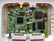
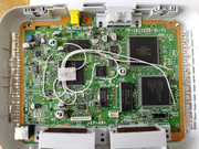
This is my arduino install on the psone PM-41
You will only need those points connected if you want to boot NTSC disks (either NTSC:J or NTSC:U/C) on a PAL PSone. The PAL PSone has a secondary region check in the boot ROM that verifies that the license area of the disc contains the PAL license data and will refuse to boot the disc if it doesn't.SteveStation wrote: ↑February 10th, 2018, 11:07 pm I have disable the ntsc fix, and now the psone works fine.
So in my case i don't need the A18 and D2 point on the bios chip?
I like my installs to be as clean as possible, i can make this on all psx version and post it, at least on pall versions.
Yes. One point under the chip.


Users browsing this forum: No registered users and 16 guests
|
Copyright © 2012-2023 PSXDEV.NET ~ No Cookies, No Tracking & No Ads. The Way the Internet Was Meant to Be ~  , "PlayStation", , "PlayStation",  , ,  , "DUALSHOCK", "Net Yaroze" and "PSone" are registered trademarks of Sony Computer Entertainment Inc. , "DUALSHOCK", "Net Yaroze" and "PSone" are registered trademarks of Sony Computer Entertainment Inc. This page is for informational use only. The user of this software, assumes full responsibility ensuring its use in accordance with local and federal laws. The software and hardware on this site is provided "as-is", without any express, implied warranty or guarantees. |